

Boiler room
The boiler room consists of:
- Biogas boilers;
- Solid fuel boilers;
- Steam superheaters;
- Steam loop;
- System of heatexchangers;
- Economizers;
- System of filters;
- Air compressors;
- Smoke exhausters;
- Fly-ash handling system;
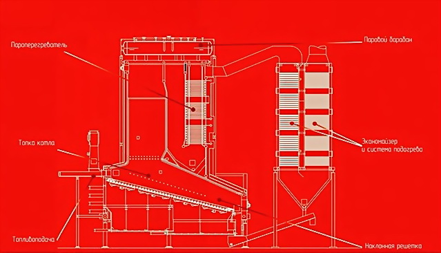
- Combustion
Within the frame of the offered methodology, the single-header boiler with additional thrust, secondary air supply to a torch and a regulated smoke exhauster was chosen. We, also, have considered variants of a pyrolysis boiler and a boiler on a fluidized bed use. But, this variant was abandoned as it is difficult to achieve steady pyrolysis process in boilers of more than 5 MW capacity. The variant of a boiler on a fluidized bed is taken as an alternative one. Separately, a biogas boiler was chosen, as biogas has its own peculiarities while being incinerated. These peculiarities are described below. We have also considered the variant of boiler that works with mixed type of fuel (RDF +biogas). This variant is chosen as an alternative one.
To achieve the set characteristics the boilre shoul meet the following characteristics:
Characteristicas of an RDF boiler:
| Maximum steam capacity | 1 МВт = 0,93 t. steam |
| Maximum steam capacity under 40 % load | 1 МВт = 1,25 t. steam |
| Maximum workinf pressure | 55,0 bar |
| Design pressure | 65,0 bar |
| Working temperature of superheated steam at 70 - 100% steam capacity | 450 0С |
| О2, dry gas | 7,0 % |
| Temperature in the combustion chamber | ~850 – 900 0С |
| Temperature of smoke fumes | not more 180 0С |
| Thermal efficiency | 89 % |
| Amount of air for combustion | 5 834 nm3/h per 1 t. fuel |
| Amount of smoke fumes | 7 265 nm3/h per 1 t. fuel |
| Compliance with NTD | PED 2014/68/CE |
Exhausts quantity:
All values of emissions boundary limits are calculated at a temperature of 273.15 K and a pressure of 101.3 kPa, and after correction for the content of output gases water vapors and at a normal O2 of 6% in daily mean:
| Dust mg/ Nm3 | Not more that 25 mg/Nm |
| CO mg/ Nm3 | 250 |
| NOx mg/ Nm3 | 250 |
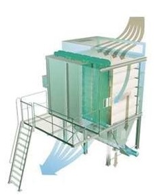
Specifics of a solid fuel boiler working on RDF. Filtration and neutralization of exhaust fumes:
- Solid fuel boiler, which works on RDF is equipped with a complex filtration system. The following filters are included into the filtration system: multi-cyclone filter with water gas cleaning (scrubber) to sieve solid volatiles and sleeve filter with PTFE coating from glass fiber. Solid volatiles go from a multi-cyclone filter to a fly-ash handling system. Also, the possibility for electrical filter installation is provided.

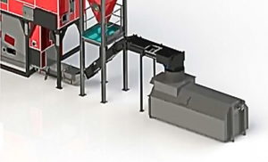
A fly-ash handling system. Ash is formed after solid fuel is combusted. In the case of RDF this figure is 10-12% of a total quantity of fuel. The boiler is equipped with an automatic wet ash-handling system from a fire-bar. Also, ash-and-slag removal system is provided under the filter. Ash is packed and buried. The possibility of its industrial use is subject to study.

- Exhaust gases afterburning system. The combustion chamber is performed in the way that exhaust gases stay at the top point of a combustion chamber for about 2 sec. before they are gone to a multi-cyclone filter. Neutralization of harmful gases is made during this time.
Biogas combustion specifics:
Under a comparative analysis of co-generation plants and boiler-turbine systems, the latest was decided on. Except that, in case that a steam-turbine complex working of RDF is included in the configuration of the plant, the advantages of RDF combustion in boilers become more substantial. Biogas has its specifics of combustion. Namely, compared with other gases, biogas requires less combustion air. Accordingly, gas burners require provision of wider jets for biogas to pass. For complete combustion of 1 liter of biogas, it is required about 5.7 liters of air, while for butane - 30.9 liters and for propane - 23.8 liters.
Superheated steam:
The final product of RDF and biogas burning is superheated steam. Steam part of a boiler consists of the following elements:
- Steam superheater;
- Feeding water circulation system;
- Economizer;
- Pumping equipment;
- Piping inside the boiler;
- Tubing;
- Feeding system for feeding water;
- Water preparation system;
Superheated steam in the general system of the methodology under consideration carries out the following basic functions: (a) feeding of the steam turbine, (b) ensuring the biological processes of digestion.
Steam turboaggregates
Turbine generator complex:
- Steam turboaggregate(s)
- Reductor;
- Generator;
- Condensator;
- Deaerator;
- Cooling system with a cooling tower;
Additionally:
- Steam extraction system;
Depending on goals that a plant should fulfill, one of three variants of turboaggregates is chosen:
- Condensing turboaggregate. Oriented for maximum electrical energy obtainment. All the exhaust steam nearly has some cathexis. Efficiency is between 28-34%;
- Turboaggregate with a regulated steam extraction. This turbine produces electrical energy and allows to extract a chosen quantity of steam. The efficiency of such a turbine depends on the amount of steam extracted.
The decision on which turbine to choose is made on the preferences of the Employer and according to the technical characteristics of an energy generating complex. Low-speed turbines have the rotor's frequefcy of 1500 – 3000 rpm. High-speed - 6000 – 9000 rpm. The higher is the frequency of a turbine the lower is its metal intensity, and consequently its inrtia. Усереднені показники енергоефективності з одиниці пару для конденсаційних турбін наступні:
- Low-speed turbines with a capacity of more than 10 МW – 0,214 МW,/1 t. steam;
- High-speed turbines with a capacity of more up to 10 МW – 0,262 МW/1 t. steam;
- Low-speed turbines with a capacity of up to 5 МW ~ 0,257 МW,/1 тн. пару;
- High-speed turbines with a capacity of more than 5 МW ~ 0,314 МW/1 t. steam;
The main characteristic of the electricity quality is a supply frequency stability. In Ukraine, the standard is 50 Hz +/- 0,2%. A sharp fall in supply frequency leads to an emergency shutoff. That is why the requirement to the stability of rotor rotation is the main priority. To ensure this stability, there is a need to ensure the stability of steam production. If the variations in steam production are essential then the preference should be given to low-speed turbines.